

Here we have it – an affordable Open Source Laser RangeFinder – OSLRF-01 from www.lightware.co.za. You can order it fully assembled and working or just PCB and optics (all other components have to find by Yourself).
So next step is connect it somehow to something. At that moment I found just one sucsess story shared online – Arduino Scanning LIDAR by Michael Ball http://arduino-pi.blogspot.com/2014/03/prototype-of-oslrf01-arduino-scanning.html. That was a very nice place to start connecting it to my Arduino UNO. Michael done it with Arduino Fio, which is 3.3V logic level board, not 5V like UNO’s. Don’t know real reasons why (maybe different voltage levels(different ADC’s), maybe different register settings for different boards), but straight out of the box I was receiving strange data. It was like added ~400cm to all my readings. OSLRF-01 was reacting to distance changes, but was very far from desired(real) values.
First I was little angry, then little depressed, but now I’m happy 🙂 because it made me dive a little bit deeper into this sensor. And I will share some findings with You.
I will not repeat info about sensor working principles, they are nicely covered by creators. I’ll try to concentrate on getting something out of it.
1. Wires
There is an illustration of simplest way to connect OSLRF-01 to Arduino UNO:

- Laser rangefinder must be powered by stabilized 12V source ( “Vin” ).
- “Zero” pin to A1,
- “Return” to A3 and
- “Sync” to Arduino’s digital 2
- Arduino board has to be powered separately by USB cable or external power source (not displayed)
Thats all 🙂
2. Signals
First is worth to mention, that without using “Control” measurements are regularly made on about 37 Hz frequency. “About” is very good description, because frequency is drifting a little all the time. Just after power-on it drifts more:

Second, illustration from official manual:
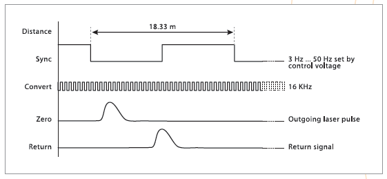
1) “Sync” signal goes low and at this moment starts measurement process.
2) Laser fires and electronics generates “Zero” impulse.
3) Light returns from target and electronics generates “Return” impulse.
Everything repeats on next cycle.
Our task is to measure time between “Zero” and “Return” and convert this difference into meaningful distance value.
From above diagram I assumed that there is plenty of time between laser fire (Zero) and Return signals. In reality I had a lot of trouble finding rising edge of “Return” signal after I found falling edge of “Zero”. Thats because if You don’t use “Control” pin on OSLRF-01 (to adjust frequency of laser fires) then “Return” signal overlaps “Zero” signal when target moves closer than 400-500cm.
Here is my real-world measurements:

3. Figuring out something
As I mentioned in part 2 – from Zero and Return signals You have somehow get distance value. User manual offers us magic formula d = ((Rt – Zt) / Sp) * 18.33 , where d – distance to target (in meters), Rt – time from falling “Sync” edge to “Return” signal, Zt – time from falling “Sync” edge to “Zero” signal, Sp – “Sync” period.
Seems easy, until You start to think what is “time from signal to signal”. Is it time from front of one signal to front of other ? Short answer – No. Long answer No, if you need to measure distances closer than 1 meter. Look at Fig.4 – 100cm 50cm and 25 cm fronts are almost the same. And it is possible to choose wrong threshold when 50cm and especially 25 cm will appear farther than 100cm. User manual recommends to measure signals “centers”, or midways between rising and falling edges. This really helps to deal with close distances. But leaves open question about choosing right threshold.
Lets look closer. We can choose “secure” (high) threshold above all possible noise levels:

Low threshold illustration:

Now lets look how Arduino actually “sees” those signals after ADC conversion. I recorded “Return” signal into big array and plotted graphs:
 |
 |
Adaptive_Return_Thresh = 0.13 * Amplitude + 10 (For 3.3V boards You have to scale it)
Of course this slows-down response a little bit (if object/sensor moves very fast, you need some time to adapt to new distance). And maybe this approach not suitable for an applications, where You don’t have luxury firing multiple times at the same target. But for me it worked very well. It even produced less noise in results:


Also I took some assumptions – “Zero” is always the same shape, same amplitude, same width, and maybe the same latency from falling “Sync” edge, but to avoid drifting problems and to be sure I still measure rising edge at constant threshold. Then adding constant half/width to detected front of “Zero”.
4. Smooth the rough edges off
But even when targets were completely still, I got some random noise on distance readings (1-2 cm order). So I went easiest way – averaged “Sync” period readings and calculated distance values. I achieved desired stability using 40 values (~1 second) of running average on “Sync” period and continuously averaging last 20 values of final distance. This maybe too slow for very fast changing environment like plane/copter or fast robot, but for natural targets like myself that was OK 🙂
Also I calibrated distance values. For example
|
|
As You see calculated values are pretty far away from what we expect. BUT making graphs out of those “errors” clearly shows easy way to make corrections. So I made simple(linear) empiric correction formulas and coded them into program. One formula for 100-500cm range, and other 0-100cm segment. I expect that from 500cm to 1000cm I would have to do another one, but I need more space for measurements 🙂
5. The results
Yeah, Jesse, we share the same feelings 🙂 Here is an example of me walking away from sensor:

5. Code
//
// OLSRF-01 for Arduino UNO code
// (c) Ignas Gramba, 2014
// www.berryjam.eu/2014/06/oslrf-01
//


#define ZERO_PIN     A1  // Arduino pin tied to Zero   pin on the OSLRF.
#define RETURN_PIN   A3  // Arduino pin tied to Return pin on the OSLRF.
#define SYNC_PIN     2   // Arduino pin tied to Sync   pin on the OSLRF.


int zero_val = 0;
int return_val = 0;
int sync_val_1 = 0;
int sync_val_2 = 0;
int amp = 0;

int zero_thresh = 40;
int return_thresh = 50;

float raw_distance = 0.0;
float distance = 0.0;

unsigned long zero_time;
unsigned long zero_time1;
unsigned long zero_time2;

unsigned long echo_time;
unsigned long echo_time1;
unsigned long echo_time2;

unsigned long sync_time_1;
unsigned long sync_time_2;
unsigned long sync_period;


// Distance average variables
const int numReadings = 20;
int readings[numReadings];      // the readings from the analog input
int index = 0;                  // the index of the current reading
int total = 0;                  // the running total
int avgDist = 0;                // the average

// Sync period average variables
const int numReadings2 = 40;
unsigned long readings2[numReadings2];      // the readings from the analog input
int index2 = 0;                             // the index of the current reading
unsigned long total2 = 0;                   // the running total
unsigned long avgSync = 0;                  // the average


void setup()
{
 pinMode(SYNC_PIN, INPUT);
 Serial.begin(57600);

 // Sync averaging itialize routine
 for (int thisReading = 0; thisReading < numReadings; thisReading++)
    readings[thisReading] = 0;

 // Distance averaging itialize routine
 for (int thisReading2 = 0; thisReading2 < numReadings2; thisReading2++)
    readings2[thisReading2] = 0;
}

void loop() {

  getSyncPeriod();      // This "Sync" period update can be done not on every loop cycle,
  AverageSyncPeriod();  // as it takes time and looses some (3) distance measurements

  // Detect Zero signal rising edge
  while ((zero_val = analogRead(ZERO_PIN)) < zero_thresh)
  zero_time1 = micros();

  // Detect Return signal rising edge based on previous measurement amplitude
  while ((return_val = analogRead(RETURN_PIN)) < return_thresh)
  echo_time1 = micros();


  // Get maximum height of Return pulse...
  amp = 0;
  while (amp <= return_val ) {
    amp = return_val;
    return_val = analogRead(RETURN_PIN);
  }

  // Detect Return signal falling edge
  while ((return_val = analogRead(RETURN_PIN)) > return_thresh)
  echo_time2 = micros();

  // New Return signal threshold for next measurement, based on the new amplitude
  return_thresh = 0.13 * (float)amp + 10;         // Pure empiric, based on observations.
  if (return_thresh < 18) return_thresh = 18;     // Make sure that threshold is over the noise

  zero_time = zero_time1 + 3500;                  // Midpoint of Zero. Full Zero signal width - 7000us, when threshold 40
  echo_time = echo_time1 + ((float)echo_time2 - (float)echo_time1)/3.0;

  raw_distance = (float)(echo_time - zero_time)/(float)avgSync * 1833.0;

  if (raw_distance > 1000) {}       // Just ignore this reading
  else{
    if (raw_distance < 220){ // RAW measure corrections if distance less than 100 cm
    distance = 0.725 * raw_distance - 56.208;
    }
    else distance = 1.078 * raw_distance - 134.05; // Empiric correction for 100cm and up
  }

  AverageDistanceReadings();

  Serial.println(avgDist);


} //loop


void getSyncPeriod(){
  //  sync_period = 2*pulseIn(SYNC_PIN, LOW); // was too big about 80us, because duty cycle not perfect 50%

  // Need to optimize, as it takes full two clocks
  unsigned long sync_period1 = pulseIn(SYNC_PIN, LOW);
  unsigned long sync_period2 = pulseIn(SYNC_PIN, HIGH);
  sync_period = sync_period1 + sync_period2;

}

void AverageSyncPeriod(){
  total2 = total2 - readings2[index2]; // subtract the last reading
  readings2[index2] = sync_period;     // Get last measure
  total2 = total2 + readings2[index2];  // add the reading to the total
  index2 = index2 + 1;                 // advance to the next position in the array
  if (index2 >= numReadings2)          // if we're at the end of the array...
  index2 = 0;                          // ...wrap around to the beginning
//  avgSync = 1;
  avgSync = total2 / numReadings2;     // calculate the average
}

void AverageDistanceReadings(){
  total = total - readings[index];   // subtract the last reading
  readings[index] = distance;        // Get last measure
  total = total + readings[index];   // add the reading to the total
  index = index + 1;                 // advance to the next position in the array
  if (index >= numReadings)          // if we're at the end of the array...
  index = 0;                         // ...wrap around to the beginning
  avgDist = total / numReadings;     // calculate the average
}
Of course its not optimized, just step-by-step implemented basic ideas, keeping everything easy to read for myself. Any improvements welcome.
6. Final thoughts
When I purchased OSLRF-01 it was priced 100$, now its price went up to 150$ and I think it’s still pretty good for this kind of device. For me it is very hard to imagine all those conversions/ detections and other magic happening at the speed of light 🙂 Do you imagine how much time light travels 50cm distance ? About 1.67 nano seconds, nano – thats one billionth part of second. Amazing. Isn’t it ?
For my next project I found (SF-02) would be more suited. If I helped You, please help me and I’ll prepare similar presentation of next laser rangefinder sensor. Thank You!
Pingback: Pew Pew! An Arduino Based Laser Rangefinder
Pingback: Pew Pew! An Arduino Based Laser Rangefinder - Tech key | Techzone | Tech data
Pingback: Pew Pew! An Arduino Based Laser Rangefinder » Geko Geek
Pingback: Creating an Arduino-based laser rangefinder | Bits & Pieces from the Embedded Design World
Pingback: Pew Pew! An Arduino Based Laser Rangefinder | Ad Pub
Pingback: Faweiz Blog 博客 – Electronics-Lab.com Blog » An Arduino Based Laser Rangefinder